
The History of Monoflo Pumps
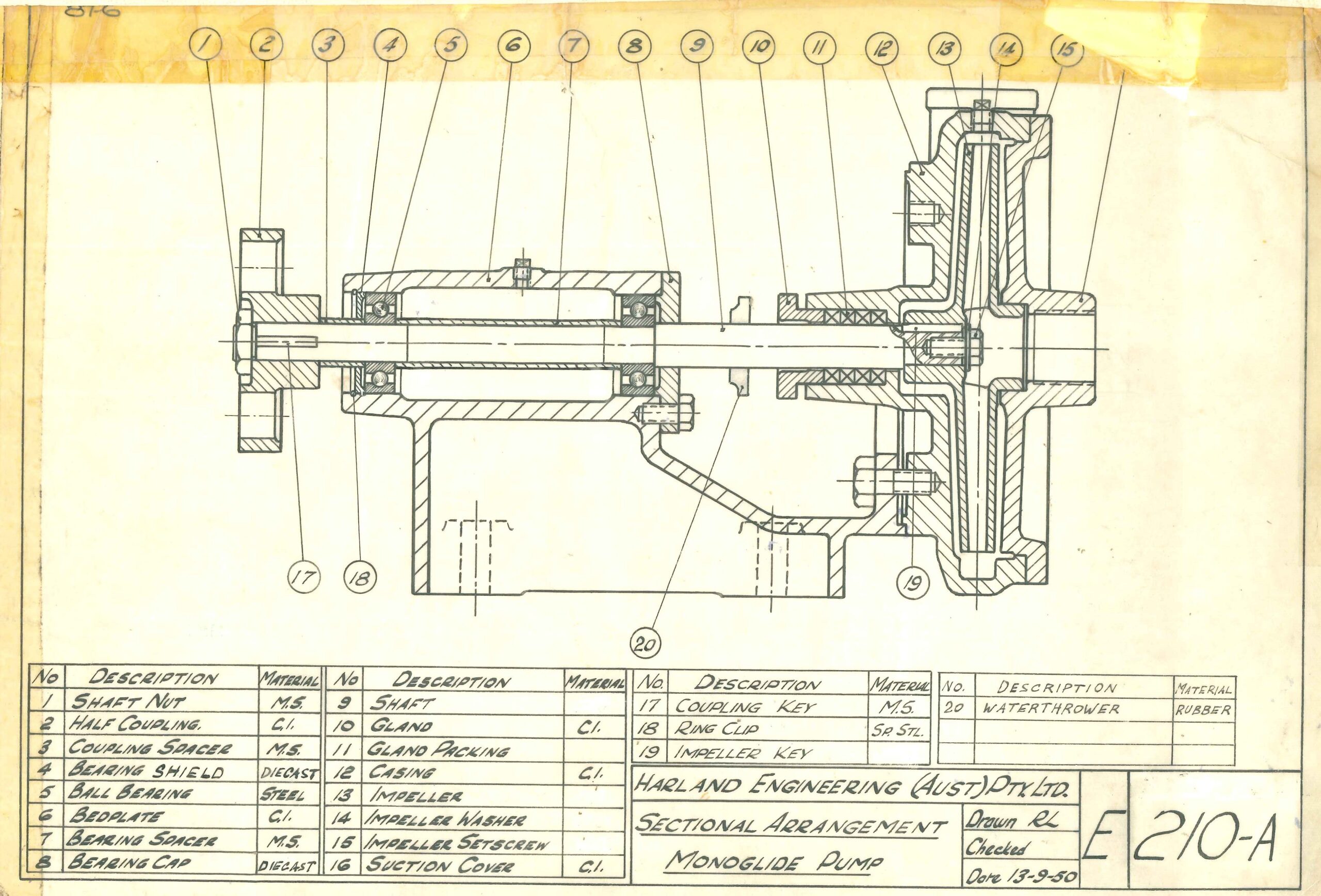
The Monoflo range of pumps was originally designed in 1946 as a general purpose unit for Agriculture and Industry. The design is an end suction pump with shaft supported by two ball bearings in a cast bearing pedestal with supports the pump. The impeller is secured to the shaft with a screw and washer while the pump half coupling is secured with a locknut which locates the ball bearing and bearing spacer.
Eleven pump sizes made up the range of pumps which were divided into three frame sizes.
These pumps were originally known as the Monoglide.
Drawing E210-A (below) shows the arrangement for the 210 frame.
| Year | Frame | Pump Sizes |
|---|---|---|
| 1946 | 210 | SSB 1½ SSB 2 SSC 1 |
| 211 | SSB 3 SSB 4 SSC 1½ SSC 2 | |
| 212 | SSB 5 SSB 6 SSC 3 SSC 4 |
In 1949 the SSB 2½ was added to the 210 Frame Pumps and the SSD Pumps introduced on the 211 frame and the 212 frame. The 313 pumps were also introduced at this time, and the arrangement for these pumps is shown on drawing E313-A.
This made the pump range as follows:
| Year | Frame | Pump Sizes |
|---|---|---|
| 1949 | 210 | SSB 1½ SSB 2 SSB 2½ SSC 1 |
| 211 | SSB 3 SSB 4 SSC 2 SSC 3 SSD 1½/2 SSD 2/2½ | |
| 212 | SSB 5 SSB 6 SSC 3 SSC 4 SSD 2½/3 SSD 3/4 SSD 4/4 | |
| 313 | SSB 8 SSB 10 |
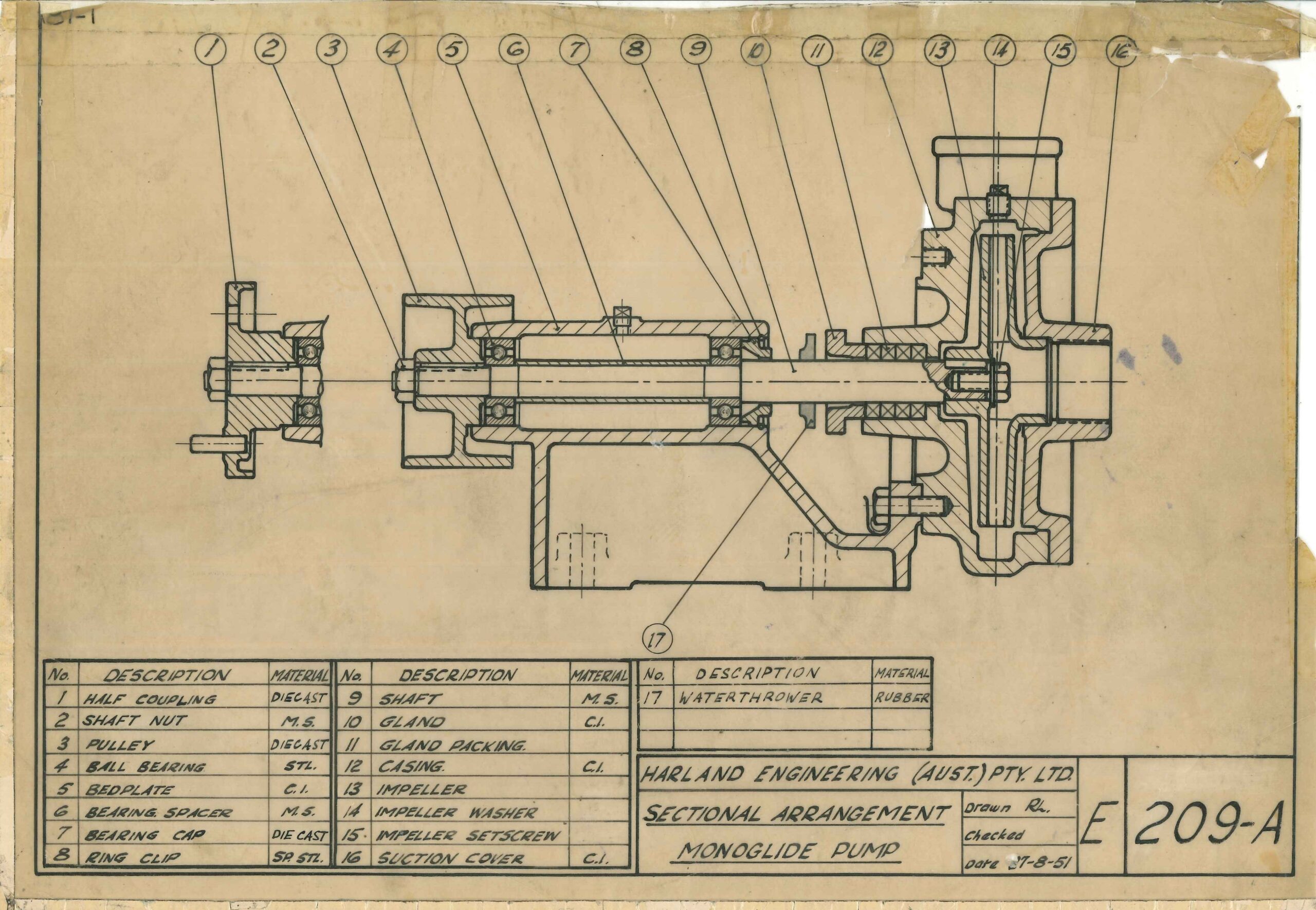
The 209 Frame pumps were designed in 1950 and these were the SSB 1/1, 1/4 and SSB 1¼/1¼. See drawing E209-A to the right.
In 1952 the SSB 12 was added to the 313 frame.
The Chokeless pumps were also introduced in 1952 and these were the SSS 3/4, SSS 4/4 and SSS 6/6. The design was based on the 212 frame but with the bedplate and bearing caps modified to give adjustment for impeller wear. The frame size of the Chokeless pumps was 380 and the arrangement as shown on drawing E380-A.
In 1955 we introduced the SSD 5″ and SSD 6″ pumps. These were designed using the 380 frame bedplate but using a larger diameter shaft and taper roller bearings. This shaft was also one inch longer than the 212 frame from the shaft end to the first fixing hole in the bedplate. See drawing E212-E.
The Chokeless pumps were redesigned in 1957 to use the same bearing arrangement as the SSD 5 and SSD 6. The location of the impeller to shaft for the Chokeless pumps was with a taper and the impeller secured with a screw and washer.
The nomenclature for the Chokeless pumps was changed from SSS to SSR. See drawing E380-C.
In 1957 the 210, 211, and 212 frame shaft arrangement was redesigned. The modifications were:
- Delete the shaft nut at the coupling end and make the coupling or pulley a light press fit on the shaft.
- Delete the coupling spacer and bearing spacer and locate the bearings on the shaft with snap rings.
- Delete the impeller screw and washer.
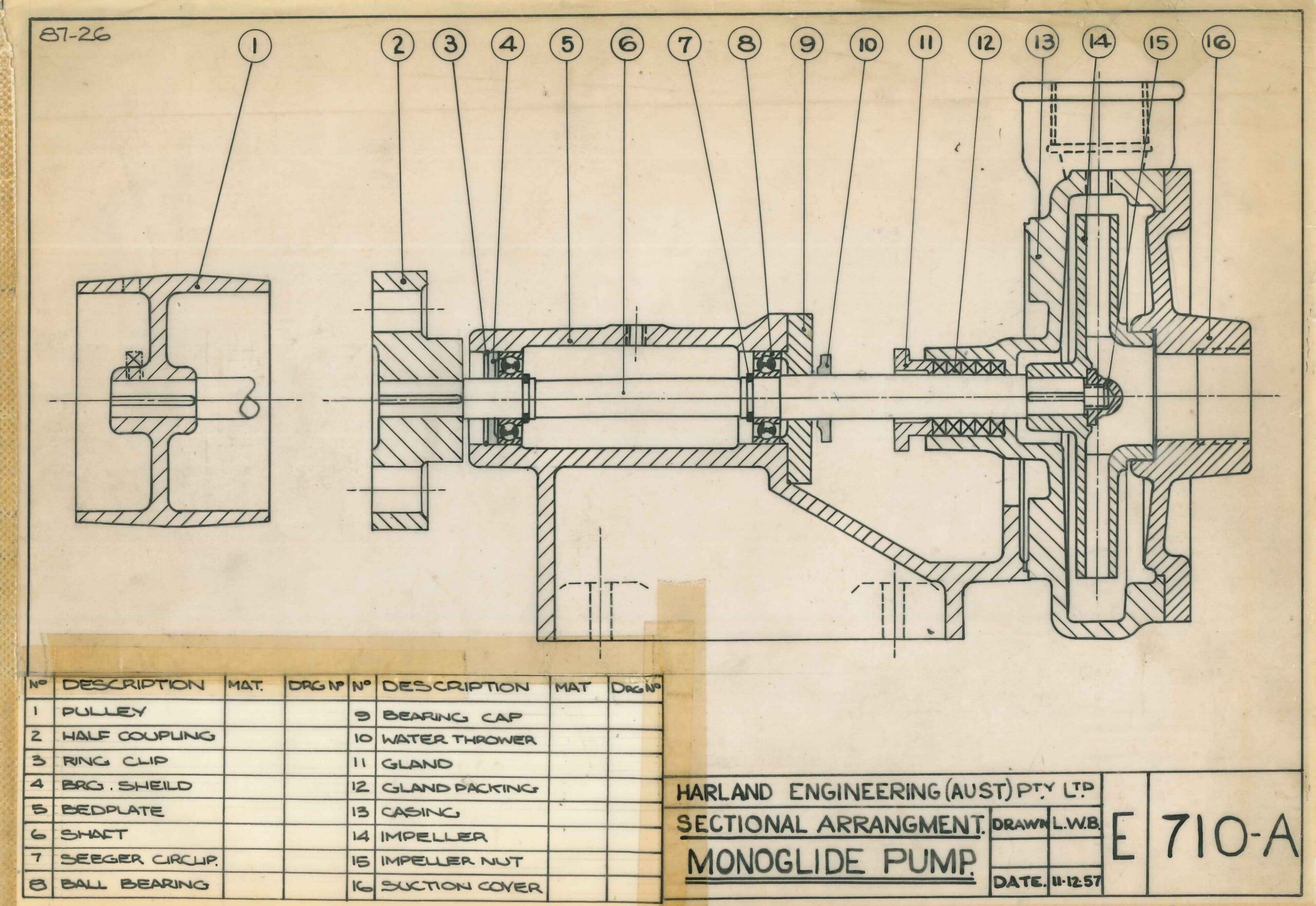
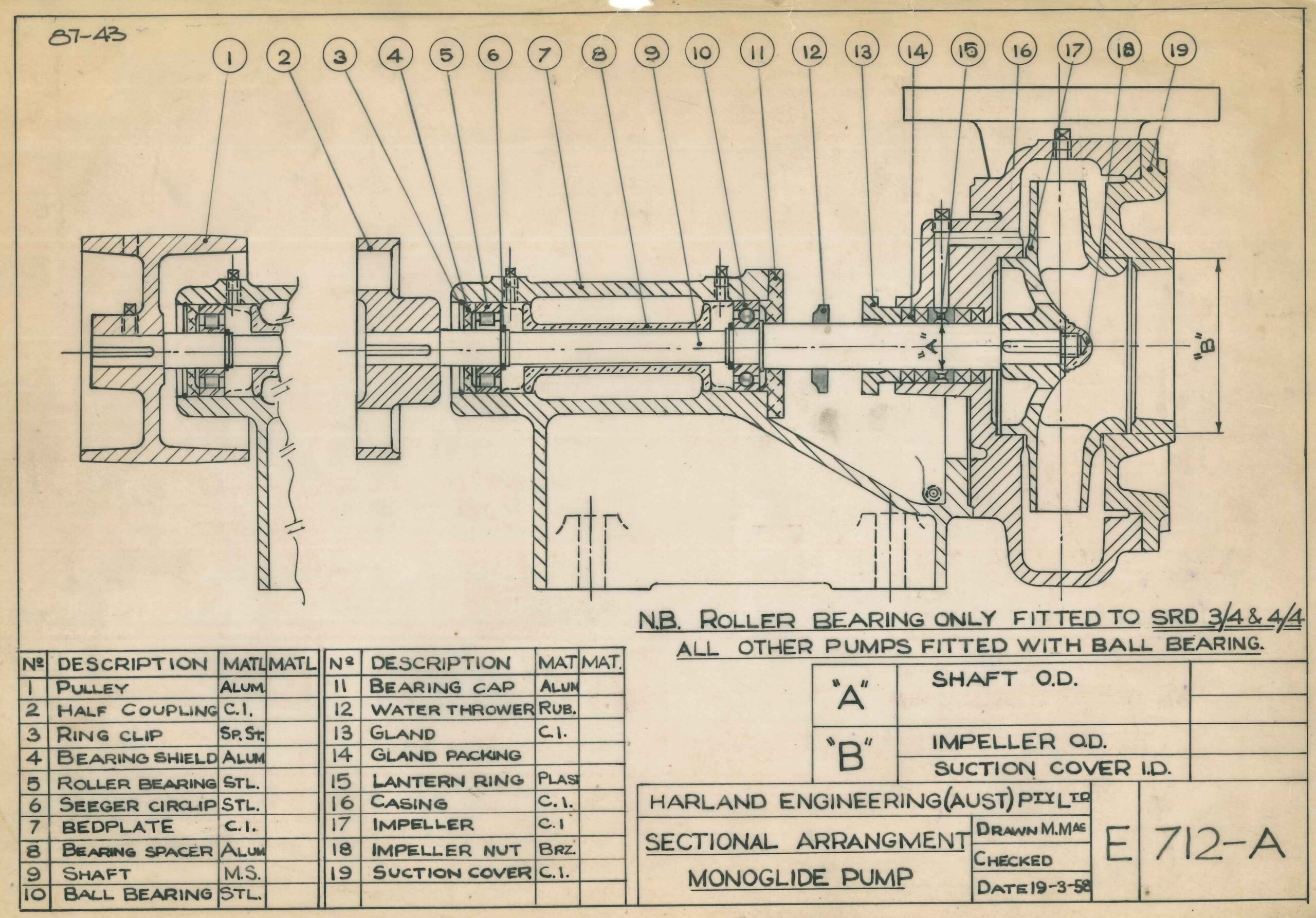
The new design was called the SR series and the frame sizes changed from 210, 211 and 212 to 710, 711 and 712. See drawing E710-A and E712-A above, for typical arrangement of the 710, 711, and 712 frame sizes. New parts and all interchangeable parts were given the new series part numbers, while parts which were not interchangeable retained their original numbers.
All SR series pumps were interchangeable with the SS pumps.
The pump range at this time being:
| Year | Frame | Pump Sizes |
|---|---|---|
| 1957 | 209 | SSB 1 SSB 1½ |
| 710 | SRB 1½ SSB 2 SRB 2½ SRC 1 | |
| 711 | SRB 3 SRB 4 SRC 1½ SRC 2 SRD 1½/2 | |
| 712 | SRB 5 SRB 6 SRC3 SRC 4 SRD 2½/3 | |
| 313 | SSB 8 SSB 10 SRB 12 | |
| 380 | SSR 3/4 SSR 4/4 SSR 6/6 SSD 5 SSD 6 |
The SSB 12 was redesigned in 1958 to give improved pump performance. This pump was designated SRB 12 and the case and impeller given 713 part numbers.
A major redesign was made to the bearing arrangement for the 710, 711 and 712 frame sizes in 1963. The new features were:
- New shape bearing pedestal to give full circle support to the casing.
- Sealed for life ball bearings.
- Bearing caps deleted.
- Bearings located with ring clips in bearing pedestal
This new design was called the VS series and the pump frames changed from 710, 711 and 712 to 910, 911 and 912. See drawings 64-13 and 64-12 for typical arrangement of this design. The 911 frame shaft was later modified to have only one snap ring and a bearing spacer used to locate the bearings as shown on drawing S65-18. All spares for 911 pumps are supplied as shown on this drawing.
All new parts and parts interchangeable from the previous SR series were given the new 910, 911, and 912 part numbers while parts which were not interchangeable retained their existing part numbers.
The pump range at this time being:
| Year | Frame | Pump Sizes |
|---|---|---|
| 1963 | 209 | SSB 1 SSB 1¼ |
| 910 | VSB 1½ VSB 2 VSB 2½ VSC 1 | |
| 911 | VSB 3 VSB 4 VSC 1½ VSC 2 VSD 1½/2 | |
| 912 | VSB 5 VSB 6 VSC 3 VSC 4 VSD 2½/3 VSD 3/4 VSD 4/4 | |
| 313 | SSB 8 SSB 10 SRB 12 | |
| 380 | SSR 3/4 SSR 4/4 SSR 6/6 SSD 5 SSD 6 |
The VSA 4 was developed in 1964 and added to the 911 frame.
The bearing pedestal for the 209 frame was redesigned to the 909 frame in 1965 to be a similar shape to the 910 frame. New pumps were added at this time to make the 909 frame pumps VSB 1, VSB 1¼, VSA 1½/2, VSA 2/2½.
The SSD 5, SSD 6 and Chokeliess pujmps were also redesigned in 1965. This was to use the 912 frame bearing pedestal modified to give axial shaft adjustment for the Chokeless pumps.
This arrangement was called the 914 frame size and the pump nomenlcature changed to VSD 5, VSD 6, VSS 3/4, VSS 4/4, VSS 6/6.
See Drawing S65-7 for VSS Chokeless pumps and S65-8 for VSD 5 and 6.
This made the full range of Monoflo pumps as follows:
| Year | Frame | Pump Sizes |
|---|---|---|
| 1965 | 909 | VSB 1 VSB 1¼ VSA 1½/2 VSA 2/2½ |
| 910 | VSB 1½ VSB 2 VSB 2½ VSC 1 | |
| 911 | VSB 3 VSB 4 VSC 1½ VSC 2 VSD 1½/2 VSD 2/2½ VSA 4 | |
| 912 | VSB 5 VSB 6 VSC 3 VSC 4 VSD 2½/3 VSD 3/4 VSD 4/4 | |
| 914 | VSD 5 VSD 6 VSS 3/4 VSS 4/4 VSS 6/6 | |
| 313 | SSB 8 SSB 10 SRB12 |
In 1970 the bearing arrangement was redesigned to delete the felt shielded bearing and include a bearing with rubber seals.
The modifications were:
- Increased shaft diameter between bearings to delete snap rings for bearing location.
- Use bearing caps to locate bearing and delete ring clips in bearing pedestal.
- Increase shaft diameter at coupling.
- Include shaft sleeve as standard feature.
- Stuffing box altered to include a packing plate.
This new design was called the VR series and the frame sizes changed from 910, 911 and 912 to 110, 111, and 112.
All parts for the VR series which were interchangeable with the VS series retained their existing part number and only those parts which were redesigned and not interchangeable were allocated the new series part numbers.
The full range of Monoflo Pumps is now:
| Year | Frame | Pump Sizes |
|---|---|---|
| 1970 | 909 | VSB 1/1¼ VSB 1¼/1¼ VSA 1½/2 VSA 2/2½ |
| 110 | VSB 1½/1½ VRB 2/2 VRB2½/2 VRC 1/1¼ | |
| 111 | VRB 3/3 VRB 4/4 VRC 1½/1½ VRC 2/2 VRD 1½/2 VRD 2/2½ | |
| 112 | VRB 5/5 VRB 6/6 VRC 3/3 VRC 4/4 | |
| 114 | VRD 5/5 VRD 6/6 VRS 3/4 VRS 4/4 VRS 6/6 | |
| 313 | SSB 8 SSB 10 SRB12 |
For all model changes from SS to SR to VS and to VR, the hydraulic performance for each pump size remained unchanged, with the exception of the SSB 12 to the SRB 12.
Due to increased operating speeds it became necessary to modify some pump sizes to improve the suction performance. This was achieved by increasing the impeller eye diameter which in turn increases the suction branch diameter.
The pumps modified were:
| Year | Original Model | Changed to |
|---|---|---|
| 1970 | VRC 1½/1½ | VRC 1½/2 |
| 1971 | VRB 2½/2½ | VRB 2½/3 |
| 1971 | VRC 2/2 | VRC2/2½ |
| 1971 | VRB 3/3 | VRB 3/4 |
| 1974 | VRC 1/1¼ | VRC 1/1½ |
| 1974 | VRC 2/2½ | VRC 2/3 |
| 1974 | VRC 1½ | VRC 1½/2½ |
The Monoflo has stayed relatively unchanged since the last major re-design, with only minor design and materials tweaks as advantageous to do so. Most of the upgrades and changes are related to bearing technology, packed glanding materials and mechanical seal materials upgrades.
Since the 1974 upgrade of the Monoflo, there are now certain models with altered and improved hydraulic characteristics, Including:
- VRB 4x4s
- VRB 6x6s
- SSB 8x8s
- VRD 3x4s
- VRD 6x6s
- VRE 3×4
- VRE 6×8
Which have either Continuously falling curves (CFC), increased performance, improved performance, or alternate Best efficiency points (BEP’s).
For spare parts, replacement pumps, or any additional information on Monoflo’s, please contact the factory.

Contact Details
Address: 31 Western Avenue, Sunshine, Victoria 3020
Postal Address: P.O. Box 348, Sunshine, Victoria 3020
Phone: +613 9464 9500
Fax: +613 9312 6371
Email: unitedpumps@unitedpumps.com.au
Website: unitedpumps.com.au
© Copyright – | All Rights Reserved
Website by Studio Rosinger